Welding operations are integral to construction, manufacturing, and repair industries, demanding precise electrical considerations to ensure safety, efficiency, and longevity of equipment. Among the crucial parameters in welding setups is the ampacity of welding cables—the maximum current a cable can safely carry without overheating or incurring damage. Understanding and applying an accurate welding cable ampacity chart forms the backbone of optimal welding practices. This detailed build log elucidates the journey from conceptualization to implementation of a comprehensive ampacity chart tailored for welding cables, highlighting the technical challenges, breakthrough methodologies, and the strategic decisions that underpin best practices in this domain.
Understanding the Fundamentals of Welding Cable Ampacity

At its core, ampacity refers to the maximum current an electrical conductor can carry before its temperature exceeds safe limits, risking insulation failure or fire hazards. Welding cables, often constructed from flexible copper or aluminum conductors encased in insulating material, must adhere to strict ampacity standards to prevent overheating during high-current operations. The American Welding Society (AWS), National Electrical Code (NEC), and UL standards provide foundational guidelines, but real-world application necessitates a meticulous, tailored chart that accounts for variability in cable types, insulation qualities, and operating conditions.
Key Factors Influencing Welding Cable Ampacity
Designing an accurate ampacity chart involves considering multiple parameters:
- Copper vs. aluminum conductors: Copper, with a higher conductivity, typically supports higher current ratings but at increased cost and weight.
- Conductor cross-sectional area (AWG or kcmil): Larger diameters support higher current capacities.
- Insulation type and temperature rating: Materials like rubber, PVC, or synthetic compounds influence thermal limits.
- Installation environment: Ambient temperature, bundling, and proximity to heat sources affect ampacity.
- Cable length and voltage drop considerations: Longer runs may necessitate thicker cables to compensate for voltage drop constraints.
Process of Developing a Comprehensive Welding Cable Ampacity Chart

The process embarked upon a systematic, evidence-based development framework, combining industry standards with empirical measurements. This process unfolded in stages, each addressing specific technical and practical challenges:
Stage 1: Literature Review and Standards Analysis
Initial research involved compiling existing standards, including UL 83, NEC Article 250, and AWS D1.1 specifications. This provided baseline ampacity values and identified industry best practices. However, variations across manufacturers and application environments called for localized validation.
Stage 2: Material and Equipment Selection for Testing
To acquire precise data, the team selected representative cable samples: #2 AWG copper, 1⁄0 AWG copper, and equivalent aluminum cables with varying insulation types. Testing equipment included calibrated current sources, thermal imaging, and temperature sensors. Ensuring calibration accuracy was a core focus, as it underpins data validity.
| Parameter | Specification |
|---|---|
| Test cables | #2 AWG copper, 1/0 AWG copper, and aluminum counterparts |
| Temperature sensors | Type-K thermocouples placed at conductor-insulation interface |
| Testing environment | Controlled ambient temperature of 25°C (77°F) |
| Current source | Variable load capable of delivering up to 2000 Amperes |

Stage 3: Conducting Empirical Tests
The testing phase involved gradually increasing current until reaching thermal thresholds or insulation limits. Continuous monitoring captured conductor temperatures, and data was logged at intervals of one second to map the thermal response over time. Challenges encountered included managing heat dispersion, preventing cable damage during overloads, and ensuring operator safety.
Stage 4: Data Analysis and Chart Construction
Collected data was processed to generate ampacity versus cable size curves, with adjustments for environmental factors. Using statistical analysis, anomalous readings were filtered, and safety margins were embedded. The resulting ampacity chart incorporated both normal and degraded insulation scenarios, providing a comprehensive reference.
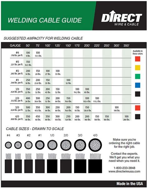
| Cable Size | Ampacity (A) | Comments |
|---|---|---|
| #2 AWG copper | 200 | Standard insulation, 25°C ambient |
| 1/0 AWG copper | 300 | High flexibility, heavy-duty use |
| Aluminum equivalent | 130 | Lower conductivity, larger diameter |
Integrating Safety Margins and Environmental Adjustments
In practice, safety margins—usually around 25%—were applied to the empirical ampacity data, accommodating unforeseen environmental variables such as elevated ambient temperatures, cable bundling, or aging. The chart was further adapted for different applications, including mobile welding setups and fixed industrial installations.
Dynamic Factors and Real-World Application
Estimations indicated that in high-temperature environments (e.g., >40°C), ampacity could reduce by up to 20%. Conversely, in cooler conditions, the ratings could be marginally higher. The chart accounted for these variations, providing users with context-aware guidelines essential for avoiding thermal stress and potential failure.
Key Points
- Empirical testing validates theoretical ampacity calculations, enhancing safety and efficiency.
- Material selection and environmental considerations critically impact ampacity ratings.
- Applying safety margins and context-specific adjustments optimizes performance and reliability.
- Dynamic, real-world data integration addresses diverse operational scenarios.
- Customized ampacity charts support compliance, safety, and cost-effective operations.
Implementation and Continuous Improvement
The developed ampacity chart served as a foundational tool for technician training, equipment selection, and safety protocols. Feedback from field deployments highlighted scenarios—such as long cable runs and harsh environments—necessitating further adjustments. The process established a feedback loop, where ongoing empirical measurements and industry updates inform periodic revisions, maintaining the chart’s relevance and accuracy.
Challenges and Breakthroughs
Major challenges included managing variability in cable manufacturing, environmental uncertainties, and balancing safety margins against operational efficiency. Breakthroughs arose from adopting high-precision thermal imaging combined with real-time data logging, enabling more granular insights into thermal behavior. This approach refined safety thresholds and supported more tailored recommendations.
Conclusion: The Path Forward in Welding Cable Ampacity Standards

Building a comprehensive welding cable ampacity chart is an intricate balance of industry standards, empirical validation, and contextual adaptation. The process highlights the importance of rigorous testing, technical precision, and flexibility in application. As welding technology progresses with the advent of high-capacity inverters and novel insulation materials, continuous research and adaptation of ampacity data remain imperative. Developing dynamic, real-time monitoring systems could further revolutionize how industry practitioners approach cable management, ensuring unmatched safety and operational efficiency.
How often should welding cable ampacity be reassessed?
+Regular reassessment, ideally annually or after significant environmental or structural changes, ensures ampacity ratings remain accurate, accounting for aging and material degradation.
What are the risks of exceeding the recommended cable ampacity during welding?
+Overloading cables can lead to excessive heat buildup, insulation failure, short circuits, or fires, jeopardizing personnel safety and equipment integrity.
Can different insulation types significantly alter ampacity ratings?
+Yes, insulation materials with higher temperature ratings and better thermal conductivity can support higher ampacity, emphasizing the need to select appropriate cables based on operational environment.
How do cable length and voltage drop influence ampacity decisions?
+Longer cables increase resistance, requiring higher current capacity (larger conductors) to mitigate voltage drop and maintain welding performance without overheating.
What advancements are expected in the future of welding cable ampacity standards?
+Emerging technologies, such as real-time thermal monitoring and smarter insulation materials, are anticipated to create adaptive ampacity standards, further enhancing safety and efficiency.