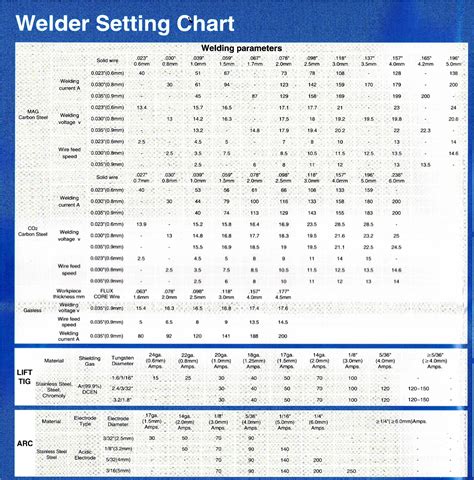
For metal fabrication enthusiasts and professional welders alike, mastering the nuances of MIG (Metal Inert Gas) welding—a technique renowned for its efficiency, versatility, and clean results—is essential. Central to achieving consistently impeccable welds is an in-depth understanding of the MIG welder settings chart. This comprehensive guide navigates the intricacies of these settings through a day-in-the-life lens, offering practical insights rooted in industry expertise. Whether you’re a seasoned professional or an aspiring welder, unlocking the secrets of your MIG welder settings chart can transform your welding outcomes, ensuring strong, precise, and aesthetically pleasing welds every time.
Deciphering the MIG Welder Settings Chart: The Foundation of Quality Welds

The MIG welder settings chart functions as the blueprint that guides welders in adjusting parameters such as voltage, wire feed speed, and shielding gas flow. These settings are not arbitrary; they are carefully calibrated to match specific materials, thicknesses, and joint configurations. For a professional welder, understanding how to interpret and adapt these charts is akin to reading a map—an essential skill developed over years of hands-on experience and technical training.
The Core Components of a MIG Settings Chart: Voltage, Wire Feed, and Gas Flow
At the heart of any MIG welder settings chart are three primary parameters: voltage, wire feed speed, and shielding gas flow rate. Precise adjustments to these settings cultivate optimal arc stability, weld penetration, and bead appearance. In practice, their interplay determines the quality and strength of the weld, especially when working with different metals and thicknesses.
| Parameter | Typical Range | Impact on Weld Quality |
|---|---|---|
| Voltage | 15-30 volts | Controls arc length and penetration; too high causes burn-through, too low causes poor fusion |
| Wire Feed Speed | 100-350 inches per minute | Affects deposition rate; incorrect settings lead to porosity or weak welds |
| Shielding Gas Flow | 20-40 cubic feet per hour (CFH) | Protects weld pool; incorrect flow can cause oxidation or porosity |

Throughout a typical day, a welder referencing and adjusting based on the settings chart might encounter different scenarios: varying material types, thicknesses, and joint geometries, all demanding a nuanced approach rooted in the foundational principles of the chart. The next sections explore these practical applications in detail.
Key Points
- Precision in settings: Fine-tuning voltage, wire speed, and gas flow ensures weld integrity and aesthetics.
- Material-specific calibration: Different metals and thicknesses necessitate tailored adjustments based on chart guidelines.
- Environmental awareness: External factors like wind or drafts influence shielding gas effectiveness, requiring on-the-fly adjustments.
- Technique adaptation: Welder skill influences how settings translate into weld quality; experience enhances responsiveness.
- Continuous learning: Regular consultation of the settings chart improves consistency and troubleshooting skills.
How a Day Unfolds: Applying Settings for Various Welding Tasks

Stepping into a typical workday, the first task often involves setting up the MIG welder for a specific project—say, welding 1⁄8-inch steel plates for a structural framework. Initially, the welder references the manufacturer’s chart, which suggests a voltage setting around 18 volts and a wire feed speed of approximately 220 inches per minute. These parameters are calibrated based on the known characteristics of the material and electrode size.
Morning: Preparing and Adjusting for Thin Materials
The morning might involve finesse work on thinner metals such as stainless steel sheets or aluminum. For these, the welder lowers the voltage—perhaps to 16 volts—and reduces the wire feed speed to prevent burn-through. Shielding gas flow, typically at 25 CFH, is monitored closely, especially in indoor environments, to prevent oxidation. During this phase, the welder frequently refers to the settings chart, adjusting parameters based on feedback from the welding arc and bead appearance.
| Sample Morning Settings for Thin Steel | |
| Voltage | 16 volts |
| Wire Feed Speed | 180 inches/min |
| Gas Flow Rate | 25 CFH |
Midday Challenges: Tackling Thicker Materials and Complex Joints
As the day progresses, the focus shifts to welding thicker components—perhaps 1⁄4-inch or 3⁄8-inch steel plates. Here, the settings must be adjusted upward; the voltage might increase to about 22 volts, with wire feed speeds of 280-320 inches per minute. The welder must also consider joint type—fillet, butt, or lap—and whether to employ spray transfer or short-circuiting techniques. The settings chart provides vital guidance but also requires interpretation based on real-world conditions.
In this context, the welder’s colloquial "day-in-the-life" involves continuous adjustments and monitoring—for example, increasing gas flow to 30 CFH if wind hampers shielding, or tweaking voltage to optimize bead penetration. Confirming proper settings involves visual inspection of the weld, checking for uniformity, lack of porosity, and adequate penetration.
Afternoon: Troubleshooting and Fine-Tuning
Post-lunch, particular attention is paid to troubleshooting issues such as porosity, inconsistent bead profiles, or excessive spatter. Using the settings chart as a reference, the welder assesses whether parameters are within optimal ranges or require fine-tuning. For instance, excessive spatter might indicate too high voltage, prompting a slight reduction. Conversely, poor penetration may suggest increasing voltage or wire feed speed. Real-time adjustments are critical, especially under variable environmental conditions or when working with reclaimed steel with inconsistent composition.
| Sample Troubleshooting Adjustments | |
| Issue | Adjustment |
| Excessive Spatter | Reduce voltage by 1-2 volts |
| Poor Penetration | Increase voltage or wire feed speed |
| Porosity | Increase shielding gas flow, check gas purity |
Advanced Considerations: Customizing Settings for Unique Projects
While the standard settings chart offers a robust foundation, complex or specialized projects often demand bespoke calibration. For example, welding dissimilar metals like aluminum to steel or working in challenging environments such as high humidity necessitates deviations from typical settings. Advanced welders employ tools like digital multimeters, arc sensors, or even welding data logs to verify parameter accuracy.
Material Considerations: Aluminum and Dissimilar Metal Welding
Welding aluminum, highly sensitive to contamination, often requires lower voltage and a different shielding gas mixture—typically pure argon at 100%, with flow rates adjusted around 20-25 CFH. Dissimilar metal welding, such as stainless steel to carbon steel, calls for nuanced adjustments: slightly higher voltage on the stainless side and strategic gas composition to prevent oxidation. These situations highlight the importance of understanding the principles behind the settings chart, enabling informed adaptation.
| Project Type | Recommended Settings |
|---|---|
| Aluminum (1/8-inch) | Voltage: 17-19 V; Wire Feed: 180-210 IPM; Gas: 100% Argon, 20-25 CFH |
| Dissimilar Metals | Adjust voltage and wire feed according to each material's specs; modify shielding gas as needed |
Conclusion: Mastery Through Continuous Practice and Reference
Understanding and applying your MIG welder settings chart is fundamental to producing durable, high-quality welds. As each project introduces new variables—material type, thickness, joint design, environmental factors—the ability to interpret and adapt these settings in real-time distinguishes proficient welders from novices. Over time, this practical mastery builds into an intuitive skill, reinforced by rigorous adherence to the principles embedded within the settings chart.
In essence, the day-in-the-life of a professional welder involves constant learning, precise adjustments, and vigilant observation. Your settings chart is not just a static reference but a living document—an essential tool that, when mastered, opens the door to flawless welds, increased productivity, and enhanced safety. Embracing this knowledge transforms welding from mere task execution into an art refined by science and experience.
How do I choose the right MIG welder settings for different materials?
+Begin by consulting the manufacturer’s settings chart, which provides baseline parameters for various metals and thicknesses. Adjust voltage, wire feed, and gas flow based on specific material properties, environmental conditions, and joint types. Experience and real-time feedback—visual or through inspection—are key to fine-tuning these settings for optimal results.
What are common mistakes when reading MIG welding charts?
+Common errors include misinterpreting the recommended ranges, ignoring environmental factors, and failing to account for differences in equipment models. Overreliance on static chart values without observational adjustments can lead to poor weld quality. Always validate settings through test welds and continuous monitoring during actual work.
Can environmental factors affect MIG welding settings?
+Yes, factors such as wind, humidity, and temperature can influence shielding gas effectiveness and arc stability. For outdoor work or in drafty conditions, increasing shielding gas flow and adjusting voltage or travel speed may be necessary. Recognizing these influences and adjusting accordingly ensures weld integrity.
How often should I revisit and revise my welding settings?
+Regularly revisiting your settings—especially when switching materials, projects, or working conditions—helps maintain weld quality. Keep a log of successful parameter combinations and refine them over time through experience. Continuous education and calibration are essential for professional excellence.